My collection of champfer tools, past and present: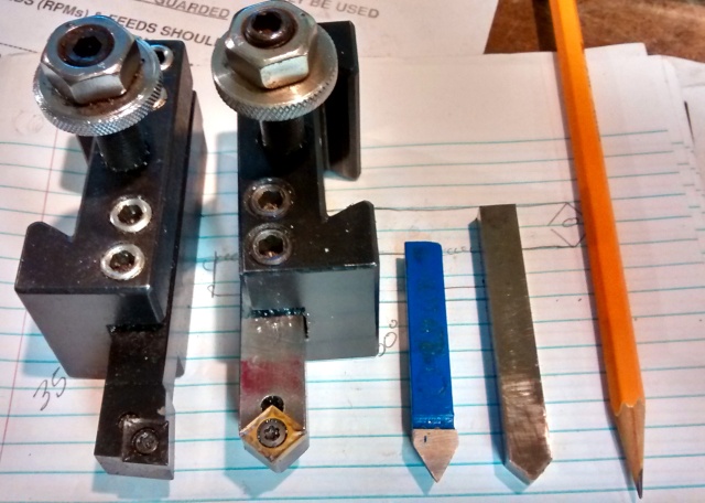 From right to left: draw and file, a HSS hand ground bit that works well but material builds up really fast so it needs to be honed often, a brazed on threading bit that works OK but the angle is usually not-quite-right and the el-cheapo bits I have are made with Velveeta carbide, finally, the newest edition, made to use the used up bits of the left most tool, both using CCMT 32.5x inserts.
I swear, there are more options for inserts than there are shoes, so I get my Carmex screwtools from Lathe Inserts; they work, the prices are good and they don’t have an overwhelming selection. But they don’t have a champfer lathe tool and when I asked about using the two unused edges of a CCMT insert, they told me the geometry was wrong. But everything else I found was quite expensive and I’d have to start a new insert collection and I can’t just throw away bits with brand new cutting edges (even though the usable edgCarmex screwes are used up).
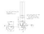
So, I’ve been sitting on it, hence the variety of tools in the photo. Plus, trying to find info on the insert and screws really taxed my ability to use google. The first C (in CCMT) means 80° diamond, the 3 means 3*1/8″ inscribed circle but what is the hole size? The screw seat is also a strange one. I bought several screws from Enco and the Seco M3.5x.6 is what I wanted (a milling cutter, not lathe, screw $5 a pop, ouch. There is also a $1 Carmex screw that will work but it is smaller. Be warned that different 3/8″ IC inserts have different sized screw holes).
Knowing that the interior angles of a quadrilateral add up to 360° means the angle I’m interested in is 50° (2*80 + 2*50 = 360). Should be simple to mill a pocket in a piece of metal to do a test, shouldn’t it?
As with a lot of things, set up is a lot harder than actually doing it. I had a really hard time trying to figure 0ut how to hold the blank for milling. I really wanted to use the rotary table; I tried clamping directly to the table, clamping to a 123 block and clamping the block to the table but what ever I did, I either couldn’t get it secure or there were too many clamps to be able to indicate the blank¹.
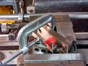 So, I used this dicey setup with a sine bar. This required two setups, which meant I had to re-indicate X,Y & Z for each edge (using the 3/16″ hole I punched in the center), something I hate to do but it worked out.
To keep the frustration to a minimum, I figured out how I could hold the part in the morning and did the machining that evening, hoping I’d think of something in between.
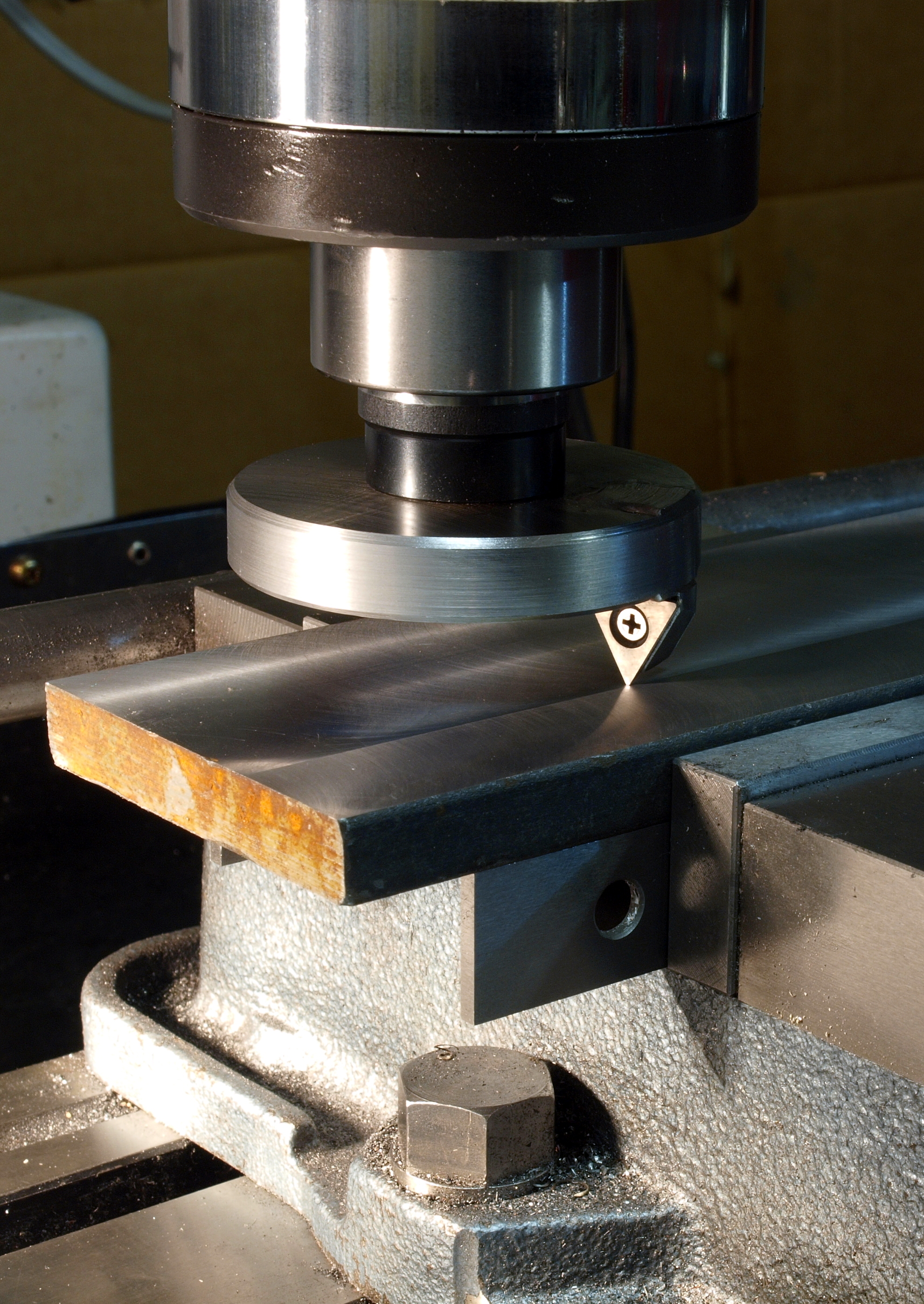
And testing indicates it works great. Although I really want to figure out how to cut this with a single set up. Without buying a CNC mill. Oh wait, I’m pretty sure my DRO angled line function will allow me to do that … bye, I’m off to the shop.
¹Doh moment – I forgot I have several toolmakers vises, which may have worked quite well, I’ll have to check. You might also be asking why didn’t I just twist the main vise? Because I don’t like to, which is rather stupid given how easy it is to re-tram it.